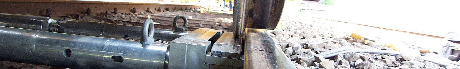
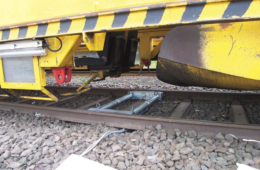
Mobile wheel load scale for the measurement and evaluation of wheel contact forces on rail vehicles.
The wheel and axle loads affect safety against derailment, the running quality, the risk of swerving and wear behavior of the locomotives and cars. It is known that after an overhaul, upgrade or repair cars or trucks with altered wheel weights can be expected. The setting dimensions and wheel and axle loads, including the total weight are therefore to be controlled carefully.
Our systems are tested according to DIN EN ISO 7500-1 as a force measuring systems from a by the EBA accredited and approved office. They are designed so that every single wheel and axle weight of the bogie can be identified and documented according to the UIC V610, DIN 27201-5 and DBAG regulations (DS 991). Our measurement system has a built-approval of DB and converts gapless the requirements and regulations of the Federal Railway Authority.
Technical Information
Advantages
The advantages of the patented measurement system at a glance:
Mechanical advantages, increased its market share, proven for years:
- Model with one-armed united tension strut for axle loads up to 25 tonnes or as heavy-duty scales up to 30 tons with a two-arm strain.
- Suitable as a stationary or mobile measuring system for all rail and rail tracks, and all workshop tracks with standard rails > S49.
- Easy transportation by separating the sensors from the bracing.
- Easy assembly by bolted bracing with cones - ready in a few minutes.
- Torsion resistant steel construction for long-term stable measuring insert.
- Driving force decoupled slants to prevent damage or overloading of the measuring cell, when approaching the measuring system.
- Floating bearing of the load cells to avoid any spurious forces in the measurement system.
- Defined calculated power dissipation of the measurement system on the rail on strip-shaped bearing parts without damage to the rail.
- Removable direction slants and wear tracks for quick passage of the built measurement system (mitigation).
- Height adjustment of the measuring system, without the remove, adaptation to different flange heights by means of simple relining lattens.
- Replaceable hardened directions slants, wear webs and pins as standardized inexpensive spare parts available.
Digital measurement technology of the latest generation:
- Mobile or stationary measurement system for wheel, axle, bogie forces (kN) or vehicle loads (tons).
- Measured is on the vertical flange the selective wheel contact force without the influence of undefined wheel contact points of the tread on the rail.
- Digital, interchangeable, addressed measuring heads guarantee the construction of complex measurement systems for up to 16 axes.
- The measuring system can be used immediately, the calibration of the digital measuring heads carried out by an accredited, EBA approved, external company ex work, the exchange or recalibration relates only to the measurement heads..
- Agreed accuracy over the entire range of the measurement path regardless of the position of the wheel.
- Digital CAN-bus controlled data transfer to the USB port of the laptop.
- Graphical display of all emergency forces and load distributions in accordance with the standards UIC V610 / DIN 27201-5 even during the measurements.
Data acquisition and analysis software in accordance with guidelines UIC V610 and DIN 27201-5
- Software works with the operating systems from Windows 7.
- The software supports the following functions:
- Hierarchically differentiated user management.
- Multilanguage -the standard version includes German and English.
- Test configuration with free distribution of measuring points positions in the test.
- Selection of the applicable test procedure of the software (UIC / TRF).
- Range management with graphical designation of series and free measuring step configuration.
- Vehicle administration vehicle-related special error limits.
- Evaluation of all measured data with determination of the wheel and axis errors, and compared with the stored maximum tolerances.
- Error calculation and report generation in accordance with the relevant regulations (DIN / TRF).
- Creating life-cycles for vehicles.
- Integrated database backup of every software start to the highest possible data security.
- Standard form set for 2-, 4- and 6-axle vehicles with motive, running and Jacob bogies (Form NEUTRAL with a placeholder for a company logo).
In the case of a failure of the original laptop the program for data acquisition and evaluation can be started of any other PC or laptop from a memory card (stick). The license is for 4 weeks off switch (emergency program).
|
Specifications
Measuring system for the detection and evaluation of wheel contact forces on the bogie
|
Measuring range
|
250/300 kN per axis
(- A system consists of two axis measurement systems.
- An axis measuring system consists of two wheel measuring systems).
|
|
Measuring range per wheel measuring system
|
|
| Scale interval |
0,1 kN
|
|
Electrical connection
|
230 V (AC) / 50-60 Hz
|
|
Nominal temperature range
|
-10 until +60 C°
|
|
Measuring devices class
|
|
|
Degree of protection
|
IP 67
|
|
Track gauge
|
1435 mm (optional others)
|
|
Rail type
|
> S49
|
| Flange heights |
22 mm until 38 mm
|
|
Width of the measuring head
|
580 mm
|
|
Active measurement section
|
|
|
Weight of a measurement headn
|
app. 60 kg
|
|
Total weight axis measuring system
|
appr. 150 kg
|
Made in Germany (EU)